This is a circuit to automatically blink the turn signal lights of a car a number of times after a short tap of the turn signal handle. This feature is often found in newer cars these days, but not in my 2000 Volkswagen Passat. Instead of buying a new car, I decided to upgraded it with an Atmel ATtiny12.
When you tap the turn signal handle shorter than a configurable time (around 300 msec by default), the turn signal lights will automatically blink a configurable number of times (3 times by default). This will not occur when you hold the handle for a longer time. Apart from this automatic mode, every blink period will always be completed, even when the handle is returned during a blink.
The behavior of the software can be controlled by a push button and a LED on the dashboard. You can change the blink count, blink interval, maximum activation pulse width, and the behavior of the LED. These settings are stored in EEPROM.
To inspect one of the settings, quickly press the button 1 to 4 times. The selected value will then be shown as a number of LED flashes. To change a setting, hold the button for longer than 0.5 seconds during the last press. In that case, the LED will turn on, and a new value may be set by quickly pressing the button the desired number of times. The available settings are:
| Count | Setting |
|---|---|
| 1 | blink count (0..5, default: 3) |
| 2 | blink interval (0..8, default: 3) |
| 3 | activation pulse width (0..8, default: 3) |
| 4 | debug level (0..3, default: 0) |
Because the I/O pins to read the button are shared with the other inputs, a button press is not recognized when the left signal light is on. The debug level controls the behavior of the LED during normal operation, and has the following meaning:
| Level | LED behavior |
|---|---|
| 0 | off |
| 1 | 2 blinks on powerup |
| 2 | 2 blinks on powerup + on when automatic blinking in progress |
| 3 | 2 blinks on powerup + on when the MOSFETs are activated |
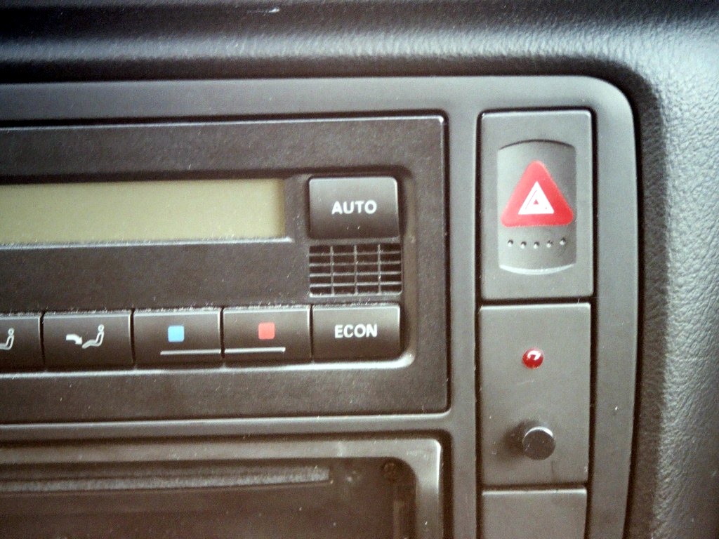
The circuit is connected to the emergency flasher relay that is integrated in the emergency flasher button in the middle of the dashboard. No existing connections had to be cut. The state of the turn signal lights is monitored by connecting the hot sides via 47K resistors to ATtiny12 inputs. I did not bother to clip the voltage to 5V, but relied on the internal protection diodes of the tiny12.
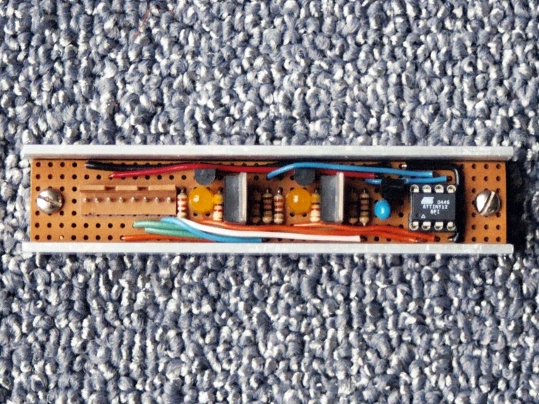
The signal lights are switched on with MOSFETs, driven by a transistor. An indicator LED lights when a MOSFET is switched on. The dashboard LED and button are controlled by the same two I/O pins that monitor the state of the signal lights by periodically changing the direction of these pins.
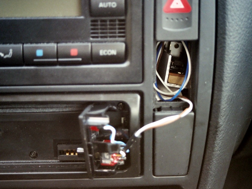
The circuit is built inside a strip of U-shaped aluminum, which is located in an unused space directly under the emergency flasher.
The LED and control button are mounted in the cover plate of this space. Click on a picture to enlarge.
The software uses a timer that generates an interrupt every 4 msec. Most of the work is done in the interrupt handler. It takes care of debouncing the inputs, and controlling the MOSFETs and the LED. The main loop only monitors the (debounced) state of the pushbutton, to interpret the button presses.
PB0 and BP1 are normally configured as outputs, to drive the dashboard LED. When the state of the signal lights is polled in the interrupt handler, these pins are switched to inputs for a short time. And when the state of the button is polled, PB0 is configured as input and BP1 is configured as output with a high level.
As a result of many changes, the interrupt handler is rather complex. I'm actually a bit embarrassed about it, but now that it works, I've lost the motivation to rewrite it.
This software is licensed under the terms of the GNU General Public License as published by the Free Software Foundation, either version 2 of the license, or (at your option) any later version.
webtag_net_streefland_avr_blink