USBtiny is a software implementation of the USB low-speed protocol for the Atmel ATtiny microcontrollers. Of course, it will also work on the ATmega series. The software is written for an AVR clocked at 12 MHz. At this frequency, each bit on the USB bus takes 8 clock cycles, and with a lot of trickery, it is possible to decode and encode the USB waveforms by software. The USB driver needs approximately 1250 to 1350 bytes of flash space (excluding the optional identification strings), depending on the configuration and compiler version, and 46 bytes RAM (excluding stack space). The C interface consists of 3 to 5 functions, depending on the configuration.
USB uses two differential data signals, D+ and D-, which are normally complementary. However, the end of a packet is signalled by pulling both signals low. Data is not transmitted directly on the USB bus, it is NRZI encoded first. This means that a "0" bit is encoded as a bit change, and a "1" bit is encoded as no bit change. After 6 "1" bits, "bit stuffing" takes place to force a change on the USB signal lines.
The software is interrupt driven: the start of a USB packet triggers an interrupt. The interrupt handler synchronizes with the sync byte, removes the NRZI encoding and bit stuffing, and stores the packed in one of the two RAM buffers. Two buffers are used so that the next packet can be received while the current one is being processed. Depending on the packet type, a reply packed may be sent back immediately in the interrupt handler.
The rest of the USB driver is written in C. A usb_poll() function must to be called periodically to poll for incoming packets. Only a single endpoint is supported at the moment. Standard control requests are directly handled by the USB driver. Other SETUP requests are forwarded to a user-supplied function usb_setup(). Support for large replies and OUT control requests is optional, see usbtiny.h.
To use the USB driver in your own application, you need to configure the macros in usbtiny.h, and provide a function usb_setup() to handle SETUP control packets. Optionally, you need to provide the functions usb_in() and usb_out(). Your code needs to call the initialization function usb_init() at program startup, and usb_poll() at regular intervals. The AVR device type and the upload command should be configured at the top of the Makefile.
This software was inspired by two similar USB projects for the AVR, especially the second one:
The IgorPlugUSB code and earlier versions of the obdev code had the restriction that the D+ signal must be connected to bit 0 of an I/O port, in addition to an interrupt input. That means that for devices like the ATtiny2313, three I/O pins are required to control the USB bus. One of the reasons I wrote USBtiny was to have more freedom over which I/O pins to use for the D+ and D- USB signals. The only restriction is that both signals should be on the same I/O port. When you select a pin for D+ that can also generate an interrupt, only two I/O pins are required. Later versions of the obdev code have also removed this restriction. The pin-change interrupt is deliberately not used, so that it remains available for other uses. Another improvement is an optional faster CRC calculation that uses a lookup table to calculate 4 bits at a time.
Apart from these advantages, I think that my code is more readable and easier to configure, but that impression may be caused by a mild form of the NIH syndrome that I'm suffering from. In any case, I learned a lot about the USB protocol, and writing the interrupt handler was a nice puzzle.
The USBtinyISP project is an AVR in-circuit programmer based on USBtiny, and is available as a kit.
An improved version of this AVR programmer called USB µISP is available at Tindie.
The AVR must be clocked with an external 12 MHz crystal. For an ATtiny2313, this means that the low fuse byte must be reprogrammed, for instance to 0xef. I also recommend to enable the BOD circuit, when available. For the ATtiny2313, this means programming the high fuse byte to 0xdb (BOD level is 2.7V).
The USB data signals are specified at 3.3V. The easiest way to accomplish this is to use a 3.3V power supply for the AVR. However, driving the USB signals with 5V seems to work as well in most cases, which may be more convenient when you need to interface to 5V peripherals. According to the USB specification, a device should not be damaged by 5V signals. I've been running the AVR and USB bus at 5V, and haven't encounter any problems so far, but I have some reports of PCs and laptops that do not work with 5V signals. In that case, you can reduce the voltage of the USB data signals by adding 3V6 zener diodes from the data signals to ground.
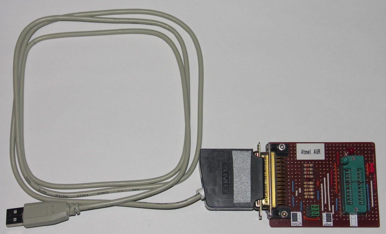
My first USBtiny application is a USB to SPI (Serial Programming Interface) converter. The SPI signals are connected to a female DB-25 connecter, so that the converter can be plugged onto my AVR parallel port programmer. Because the most important parallel port signals are connected to the DB-25 connecter, the same hardware (with different firmware) could be used to control other parallel port devices. That is also the reason why I connected the ACK signal to the INT1 pin. Below is the schematic of the USB interface to my parallel port programmer.
My AVR parallel port programmer follows the bsd design from Brian Dean. For safety, I've used series resistors in the output signals. The Atmel device is powered by the data lines D1-D3, via 220 Ohm resistors. D0 is used to control a LED. Here is an ASCII-art version of the schematic:
DB25 male                          ATtiny2313
---------                          ----------
18 GND ----------------------+---- 10 GND
 2 D0  ---- 330 ---- LED ----+
 3 D1  ---- 220 ---+
 4 D2  ---- 220 ---+-------------- 20 VCC
 5 D3  ---- 220 ---+
 7 D5  ---- 1K -------------------  1 /RESET
 8 D6  ---- 680 ------------------ 19 SCK
 9 D7  ---- 1K ------------------- 17 MOSI
10 ACK --------------------------- 18 MISO
The USBtiny circuit may be powered via the diode at pin 14 of the DB-25 connector to enable reprograming the ATtiny2313 in-system. This requires an adaptor cable between another SPI programmer and a DB-25 male connector (see README for details).
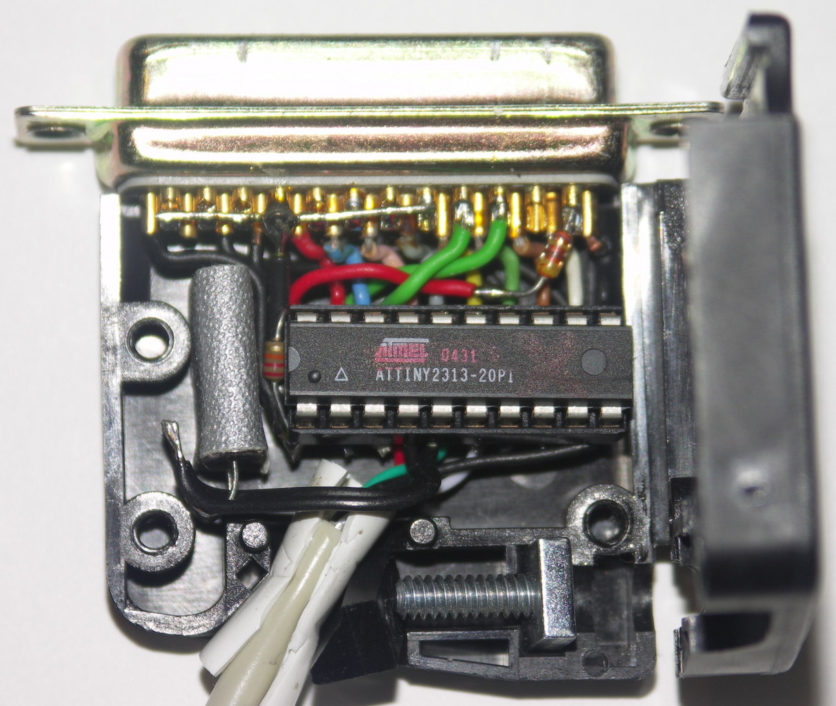
Here are pictures of the converter attached to the parallel port programmer, and a closeup of the circuit, which is built into the DB25 enclosure (click to enlarge):
Bit-banging the SPI signals via USB turned out to be very slow. To get reasonable programming speeds, I've moved the SPI algorithm into the AVR. This means that you can send a 32-bit SPI command in a single USB packet. In addition, you can read or write up to 255 bytes from/to flash or EEPROM in a single control transfer.
The distribution includes a patch for avrdude-5.4 that adds support for controlling this SPI converter. The programmer name is "usbtiny". You can use the -B option or the "sck" command to specify the minimum SCK period in microseconds (range: 1..250, default: 10). Native support for USBtiny was added in avrdude version 5.5.
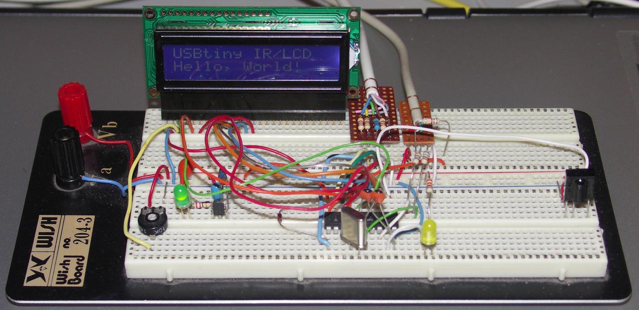
A second USBtiny application is a receiver for infrared remote controls that can be used with the LIRC package. The firmware stores the mark/space timings from a TSOP1738 IR decoder in a buffer that is polled by a LIRC device driver. As a visual feedback, a LED is flashed when a signal is being received. As an additional (optional) feature, a 2x16 LCD display is attached to PORTB. You can control the display via the USB bus. Below is the schematic of the circuit. A pull-down resistor at PB3 prevents a hang in the LCD initialization code when no LCD is attached to PORTB. You can disable the LCD code by setting the LCD_PRESENT macro in main.c to 0.
I adopted the "IgorPlug-USB" protocol, so that the existing LIRC device driver "igorplugusb" could be used without modifications. Nevertheless, patches for lirc-0.8.0 and lirc-0.8.2 are included that improve the reliability.
Here is a picture of the prototype on a breadboard (click to enlarge):
Included in the release is a third application called "usbtinyisp". This is a modified version of the SPI convertor application, that was adapted for use in the USBtinyISP AVR programmer. The code works for both v1.0 and v2.0 devices.
The subdirectory "template" contains a minimal template application that can be used as a starting point for new USBtiny applications.
The software was developed on a Linux system. In addition to standard tools like GNU make, you need the AVR versions of gcc, binutils and glibc to build the code: On a Debian/Ubuntu system, you can apt-get the following packages:
To upload the code to an AVR, I use avrdude with a parallel port programmer.
I initially used gcc-3.4.3 with the -Os option, which generates reasonable compact code. Unfortunately, newer versions like gcc-4.1.0 generated about 10% more code, and as a result, the application code did not fit in 2K anymore. To make it fit, I had to remove the optional vendor and device strings, by undefining the USBTINY_VENDOR_NAME and USBTINY_DEVICE_NAME macros. Fortunately, code generation has improved in later versions such as gcc-4.3.4.
The schematics were created with gschem, from the geda-gschem package. The conversion to Postscript is done with a script that invokes gschem non-interactively.
Included in the distribution is a Python module usbtiny.py that defines a class USBtiny that can be used to communicate with the USBtiny firmware. This class is used by the test scripts.
The usbtiny.py module uses a Python wrapper around libusb that is generated by Swig. With this module, you can control an USBtiny device with just a few lines of Python code.
The USBtiny software is licensed under the terms of the GNU General Public License as published by the Free Software Foundation, either version 2 of the license, or (at your option) any later version.
webtag_net_streefland_avr_usbtiny