
The purpose of this project is to make it possible to remotely switch on a Webasto Thermo Top C water heater that is used to pre-heat the heating system of a car without starting the motor. Instead of adding an additional wireless transmitter and receiver, I've used the existing remote control of the central door locking system.
The system was built for a Volkswagen Transporter T5 with a water heater that has a programmable timer, but no remote control. When you press the "door close" knob on the remote control of the central door locking system when the doors are already closed, the car responds with a short flash (+/- 200 msec) of the turn signal lights. I've built a circuit with an ATtiny12 that monitors one of the turn signal lights, and turns the heater on when a specific pattern of pulses is detected. The heater is switched on by simulating two button presses on the control unit.
The switch-on pattern is 3 "door close" signals with a pause of 1 to 3 seconds between consecutive pulses. Normal use of the turn signal or emergency flasher results in pulses that are too long and intervals that are shorter than 1 second, so there is no risk of accidentally triggering a heater start. To confirm the reception of the switch-on command, the right turn signal light is slowly flashed two times. The heater is started after an additional delay of 10 seconds, during which the start may be aborted by sending an additional signal. An aborted command is confirmed by 3 short flashes of the right turn signal light. The heater may also be switched off remotely, by sending 2 instead of 3 "door close" signals, which is confirmed by a single slow flash.
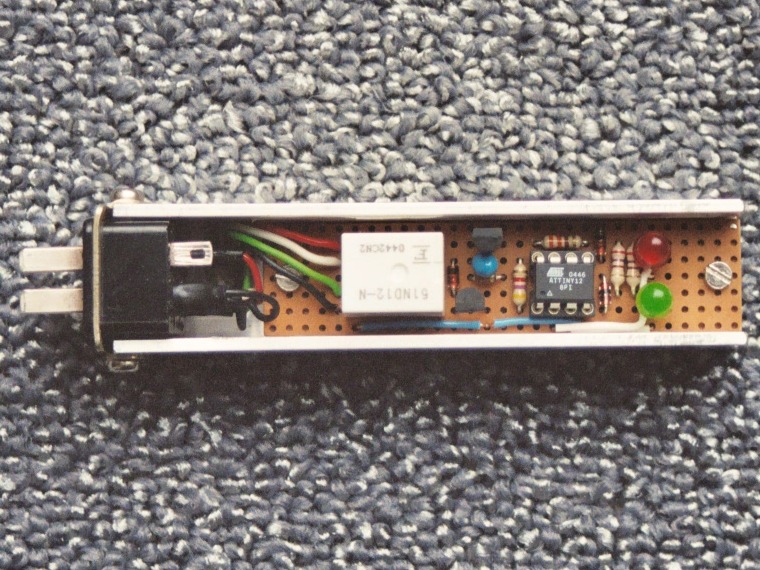
The hardware is pretty straightforward: an ATtiny12 with one input and two outputs. The input is connected to the right turn signal light, clipped to 5V. One output switches a relay that turns on the right turn signal light, and the other output drives an optocoupler that closes one of the buttons on the heater control unit. The two remaining pins drive diagnostic LEDs. The brown-out detection of the ATtiny12 is enabled at 2.7V.
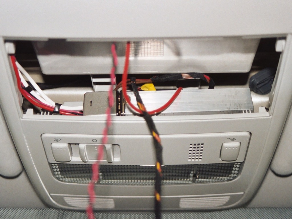
I've built the circuit inside a strip of U-shaped aluminum, which is stashed behind the heater control unit in the roof (click to enlarge):
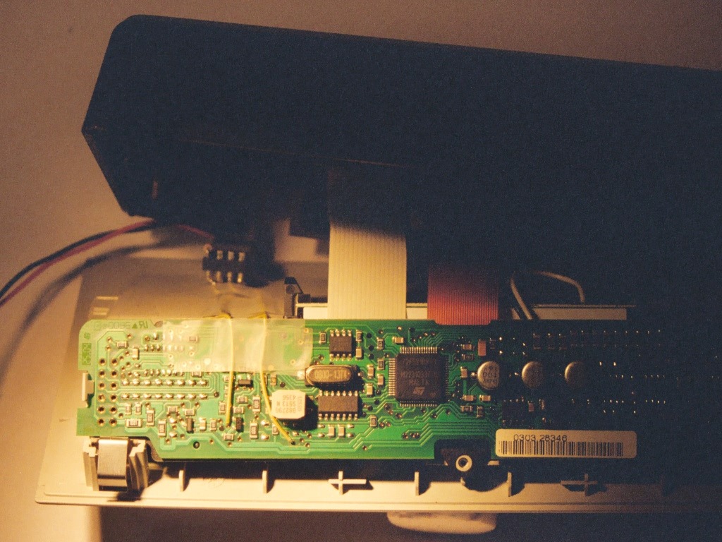
The optocoupler that shorts the start button is built into the heater control unit. I made the button connections inside the unit by inserting wirewrap wires into two tiny holes in the PCB, so that I could avoid soldering the PCB with SMD components. Here are pictures of the optocoupler inside the heater control unit (click to enlarge):

Since this circuit is always switched on, the power consumption should be as low as possible. For that reason, I used an LP2950CZ low-power regulator, which results in a total power consumption of only 0.18mA. I found out the hard way that it is always a good idea to read the datasheet. When I connected the circuit to the battery, the ATtiny12 would sometimes not start up, and the voltage regulator would get pretty hot. This problem did not occur during tests with a 12V power supply. It turned out that the regulator was oscillating because the output capacitor was not large enough, something the datasheet warns about. After replacing the capacitor, the regulator worked OK.
The software uses a timer that generates an interrupt every 4 msec. The interrupt handler increments a saturating 8-bit counter that is used for delays and timeouts. It also shifts the state of the right turn signal light into a register. When this register contains 0x00, the light is considered off, and when it contains 0xff it is considered on. All other values are ignored to avoid problems with bouncing contacts or spikes.
Normally, the ATtiny12 is sleeping in powerdown mode. It only wakes up on timer or pin-change interrupts. The pattern detection cycles starts by waiting for a low signal for more than 1 second. After that, the number of high pulses is counted, but when a high pulse is longer than 250 msec, or the interval is shorter than 1 second, the detection cycle is restarted. The counting stops when no new pulse is seen for 3 seconds. When the final count is not 2 or 3, the cycle is also restarted.
After a successful detection, the command is confirmed by flashing the turn signal light. During the next 10 seconds, the state of the light is monitored, to check for an abort command. Finally, either 2 or 1 button presses are simulated, depending on the number of pulses: 2 to switch the heater on, and 1 to switch it off.
The diagnostic LEDs show the current state of the software in the following way:
This software is licensed under the terms of the GNU General Public License as published by the Free Software Foundation, either version 2 of the license, or (at your option) any later version.
webtag_net_streefland_avr_webasto