 Batwatch
 Batwatch
Batwatch is a simple monitor for a solar panel battery charger, using an Atmel ATtiny13V. It periodically measures the charge current and battery voltage, and shows them by blinking two LEDs. I built this circuit into the plug of a VW solar charger panel that is used to prevent a discharge of the battery when a car is not used for some time. A modern car contains a large amount of electronics, and a quiescent current of 40-50mA (about 1Ah per day!) is considered "normal".
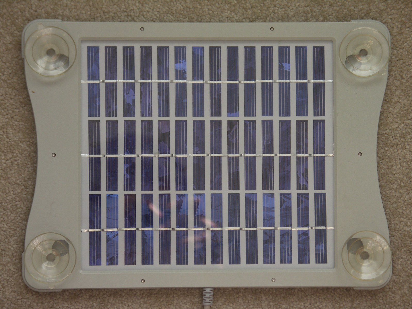
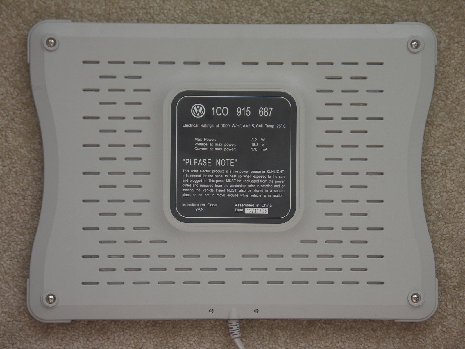
I got the solar panel on eBay. These panels seem to be delivered with new VW cars in the USA. You attach the panel against the windshield with suction pads, and plug it into the cigarate lighter. The maximum power is specified as 170mA at 18.8V, but you need very bright direct sunlight, probably somewhere near the equator, to achieve that.
This is what the solar panel looks like (click to enlarge):
Because I wanted to keep an eye on the battery condition and charge current without opening the car, I devised a circuit that shows the voltage and current visually, by blinking a red and green LED. The charge current is determined by measuring the voltage drop over a 10 ohm series resistor. Two A/D inputs are used to measure the voltage before and after the resistor, which is the battery voltage.
When you look closely at the photo of the circuit, you may notice that it actually contains two 10 ohm resistors. That is because I first used a 5 ohm series resistor, but the voltage drop turned out to be too small to get reliable current readings. The internal resistance of the solar panel is pretty high anyway, so the additional 5 ohm does not cause a significant charge current reduction.
To keep the power consumption low, I used the low-power voltage regulator LP2950CZ instead of a plain 78L05. The duty-cycle of the (low-power) LEDs is rather low, so the avarage total power consumption is about 1mA. The internal BOD circuit is enabled and set to a voltage of 4.3V.
Here are pictures of the outside and inside of the 12V cigarette lighter plug (click to enlarge):
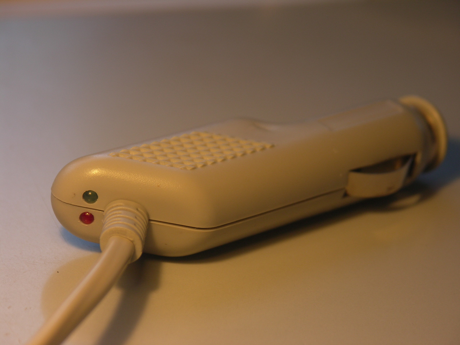

Every couple of seconds, the software samples the two analog inputs, calculates the charge current and battery voltage, and shows the voltage on the red LED and the charge current on the green LED. The voltage is shown in units of 0.1V using three decimal digits, and the current is shown in units of 10mA using two decimal digits. Each digit is represented by a number of short flashes corresponding to the value of the digit. A zero is represented by a single longer flash. When the charge current is below 10mA (after rounding) or negative, the green LED is not turned on at all.
I use 4 times oversampling to get an 11-bit result, following the technique described in the Atmel application note AVR121. I'm not sure if there is enough noise on the inputs to actually increase the resolution, but it will not hurt either. The raw A/D reading is converted to a voltage using a separate pair of offset/gain constants for each input. These constants are derived from the calibration data stored in the EEPROM.
To save power, all delays are implemented by executing one or more sleep instructions which cause the CPU to idle until the next timer interrupt. The interrupt frequency is 100 Hz, so each sleep pauses up to 10 mS.
The device must be calibrated before it can show reliable figures. For each channel, samples of exactly 8V and 12V are taken and stored in EEPROM. At program startup, these values are transformed to offset/gain pairs that are used to convert a sample to a voltage.
To calibrate the device, disconnect the battery and make sure that the solar panel is covered. Now the following steps have to be followed:
This software is licensed under the terms of the GNU General Public License as published by the Free Software Foundation, either version 2 of the license, or (at your option) any later version.
webtag_net_streefland_avr_batwatch